Create Compute Shader

You need the following Scenome® modules to complete this exercise: Scenome® Platform Binaries, Scenome® Compute Module

In this exercise you'll learn to create a document that contains a compute shader, how to write into a texture with the compute shader, and how to visualize the results of the compute shader with a vertex and fragment shader. This exercise requires GLSL version 430 or higher (this exercise could work in GLSL 400 or higher if your OpenGL driver has compute shader extensions).

Start The Shader Application

  1. Start the Shader app. (Start » Programs » Scenomics » Shader) or (Windows® key and then type 'Shader' to find the app icon.)

    The application displays a splash screen and then the application desktop appears. The main menu is composed of three items that contain commands relevant to the current context (which is an empty document). The interface changes when you create a new file or load a file from disk.

    This is a picture of the desktop.

Create New Document

  1. Select File » New » Shader from the main menu.

    The software displays a wizard that allows you to specify the parameters of your new shader. The Profile shown below is 460 core, but you will see the highest GLSL version available on your machine. NOTE: You will not see video or compute shader options in the wizard dialog if you do not have the video add-on module installed.

    This is a picture of the new project dialog.
  2. Type User Fill in the field named Name.

    Copy Text To Clipboard

    User Fill
  3. Set Profile to the highest value available such as 460 core.

    Note that your GPU must support GLSL 430 or higher, or support compute shaders via OpenGL® extensions, in order to proceed. Otherwise you will not be able to set Add Compute Support to true and you will not be able to proceed with this exercise.

  4. Set Add Compute Support to True.

  5. Hit ENTER or click OK when you are finished.

    The application creates a new shader document and the main menu options change. You can see the hierarchy on the left, the rendered shader with geometry in the middle, and the property sheet on the right. Shader compiler error messages are shown in the output window below. The shader sets the fragment color to red and does no other work.

    This is a picture of the workspace.

    If the shader compiled successfully, you should see a red square in the center of the worksheet.

  6. Select File » Save from the main menu.

Examine The Document

  1. Select Desktop » Clear Output from the main menu.

  2. Examine the main menu and select Graph » State » Expand All Tree Items. ( Or hit ALT + X ).

    This expands the graph so that you can see all the nodes. As you can see, this shader is a composite data structure made from a set of atomic types. The template document used to create the new file was built with a Scenome application named Graph. You can build your own templates, but this is covered in a later exercise.

    NOTE: You can hover over each node icon, in the image below, for a description of the node and its function.

    That covers the basic information about the graph.

Examine The <Program>

  1. Examine the hierarchy and move the mouse over the <Program> named Compute.

    Notice that you can see the GLSL version, profile, and source code locations. Many nodes, but not all of them, display useful information if you hover over them.

    This is a picture of the Program node tooltip.

Copy The Compute Shader Path

  1. Examine the hierarchy and right click over the <Program> node named Compute. This is a picture showing the location of the Compute program.
  2. Choose Copy Source Path » Compute Shader from the listed options.

    This displays a dialog that allows you to select GLSL shader source code (and any include files). The file path of the source item you select will be copied to the Windows® clipboard so you can open it in a text editor. This is a picture of the source code used by the <Program> node fragment shader.

  3. Select user_fill_compute_shader.glsl and click OK or hit ENTER when you are finished.

    This copies the absolute path to the fragment shader source code to the Windows® clipboard. For example, a file path like the following: D:\Release6\Content\Library\Shader\User Fill\460\user_fill_compute_shader.glsl is copied to the clipboard.

Implement Compute Shader

  1. Start a text editor of your choice and select the option to open a file from disk.
  2. Select CTRL + V to paste the fragment shader file path (into the place in the dialog where you specify the file to open) and open the file.

    This is the basic compute shader. Note that your #version 460 declaration might be different, depending on the highest GLSL version on your machine.

    // #version 460
    // The version number is automatically injected by the application.
    // It is included above for reference purposes only.
    
    #extension GL_ARB_compute_variable_group_size : enable
    #ifdef GL_ARB_compute_variable_group_size
       layout( local_size_variable ) in;
    #else
       layout( local_size_x = 32, local_size_y = 32, local_size_z = 1 ) in;
    #endif
    
    void main(void)
    {
    }
    
  3. Replace your compute shader source code with the following:

    Copy Text To Clipboard

    // #version 460
    // The version number is automatically injected by the application.
    // It is included above for reference purposes only.
    
    #extension GL_ARB_compute_variable_group_size : enable
    #ifdef GL_ARB_compute_variable_group_size
       layout( local_size_variable ) in;
    #else
       layout( local_size_x = 32, local_size_y = 32, local_size_z = 1 ) in;
    #endif
    
    layout( rgba32f ) uniform image2D dst_image;
    
    void main(void)
    {
       ivec2 pos = ivec2( gl_GlobalInvocationID );
    
       vec4 results = vec4( 0.5, 0.5, 0.5, 1.0 );
       imageStore( dst_image, pos, results );
    }
    
  4. Save the changes to the compute shader.
  5. Return to the running Shader application.

Rebuild The Document

  1. Select Graph » Build All from the main menu.

    The software presents the build warning dialog.

    The software warns you that document rebuilds can cause changes to shader appearance. During a rebuild, the shader source for all <Program> nodes and ( and <Program> nodes specified by <ProgramExecute> nodes ) in the document is traversed and built into a .BOX file that contains nodes representing all declared uniforms, uniform buffers, shader buffers, and structs. This information is used to automatically add the correct resources to the document and to delete obsolete resources.

  2. Click OK to proceed.

    The application rebuilds the document and displays build information in the output window.

    --- <Building Project 'D:\Release6\Content\Library\Shader\User Fill\User Fill.box'> ---
    
    Rebuilding Shader Resource Documents...
    
    Rebuild succeeded: D:\release6\content\library\shader\user fill\460\user_fill_compute_shader.glsl
    Rebuild succeeded: D:\release6\content\library\shader\user fill\460\user_fill_vertex_shader.glsl
    Rebuild succeeded: D:\release6\content\library\shader\user fill\460\user_fill_fragment_shader.glsl
    
    Updating document contents...
    
    Adding to <SamplerPaletteNode> 'Samplers' <SamplerNode> 'layout( rgba32f ) uniform image2D dst_image'
    
    Build completed.
    

Examine The Document

  1. Select Graph » State » Expand All Tree Items from the main menu.

    The graph looks like this. There is a new <SamplerNode> named layout( rgba32f ) uniform image2D dst_image that matches the declarations in the shader source code. In the image below, the new node is highlighted red for illustrative purposes (but it isn't highlighted in your document).

    This is a picture of the graph.

Create A New <Texture>

  1. Examine the hierarchy.
  2. Right click over the <SamplerNode> named layout( rgba32f ) uniform image2D dst_image and select Create Texture... from the listed options.

    The application displays the create texture dialog.

    This is a picture of the create texture dialog.
  3. Set Channel 0 Initial Value to 1.0.
  4. Set Channel 1 Initial Value to 1.0.
  5. Set Channel 2 Initial Value to 1.0.
  6. Set Channel 3 Initial Value to 1.0.
  7. Click OK or hit ENTER when you are finished.

    The software asks if you wish to save the file to disk.

    This is a picture of the save texture prompt.
  8. Click YES.

    The software presents the file save dialog and prompts you to specify the filename to use to save the texture to disk. We'll just use the file name dst_image.image being suggested by the application, but we could type our own file name here if we needed.

    This is a picture of the file save dialog.

    Note that .IMAGE is Scenome's own image file format.

  9. Click Save.

    The application saves the file to disk and adds a new <Texture> node to the graph.

Examine The Document

  1. Examine the main menu and select Graph » State » Expand All Tree Items. ( Or hit ALT + X ).

    This is the new <Texture> that the compute shader writes. We filled it with basic values of 1.0 so that we can debug easily and check if our writes are working. In the next section, we'll learn how to visualize the texture written by the compute shader so that we know it works.

    This is a picture of the graph.
  2. Select File » Save from the main menu.

Copy The Fragment Shader Path

  1. Examine the hierarchy.
  2. Right click over the <Program> named Program and select Copy Source Path » Fragment Shader. This is a picture of the graph.

    The software presents a dialog that allows you to select a shader source file. This is a picture of the dialog that allows you to select a fragment shader or include file.

  3. Select user_fill_fragment_shader.glsl from the listed options.

    This copies the absolute path to the fragment shader source code to the Windows® clipboard. For example, a file path like the following: D:\Release6\Content\Library\Shader\User Fill\460\user_fill_fragment_shader.glsl is copied to the clipboard.

Implement The Fragment Shader

  1. Start a text editor of your choice and select the option to open a file from disk.
  2. Select CTRL + V to paste the fragment shader file path (into the place in the dialog where you specify the file to open) and open the file.

    This is the fragment shader. Note that your #version 460 declaration might be different, depending on the highest GLSL version on your machine. You can still follow this exercise even if the shader code is different. Just follow the steps below and make the same changes in the same locations.

    // #version NNN
    // The version number is automatically injected by the application.
    // It is included above for reference purposes only.
    #include <SPA_Version.glsl>
    #include "user_standard_pipeline_attributes.glsl"
    
    in Data { vertexData attributes; } DataIn;
    out vec4 fragColor;
    
    void main(void)
    {
       fragColor = vec4( 1.0, 0.0, 0.0, 1.0 );
    }
    
  3. Replace your fragment shader source with the following:

    Copy Text To Clipboard

    // #version NNN
    // The version number is automatically injected by the application.
    // It is included above for reference purposes only.
    #include <SPA_Version.glsl>
    #include <SPA_Constants.glsl>
    #include <Modules/SPA_EditStateFragmentColorOverride.glsl>
    #include "user_fill_attributes.glsl"
    
    in Data { vertexData attributes; } DataIn;
    
    // We need width and height in case
    // the GLSL version is less than 430.
    // the function imageSize() is only
    // available for GLSL 430 and higher.
    uniform int image_width;
    uniform int image_height;
    layout( rgba32f ) uniform image2D dst_image;
    
    out vec4 fragColor;
    
    void main(void)
    {
       fragColor = vec4( 1.0, 0.0, 0.0, 1.0 );
    
       #if __version__ < 430
       ivec2 src_dims = ivec2( image_width, image_height );
       #else
       ivec2 src_dims = imageSize( dst_image );
       #endif
    
       ivec2 coords = ivec2( DataIn.attributes.texcoord * vec2( src_dims ) );
       vec4 pix = imageLoad( dst_image, coords );
    
       fragColor = pix;
       SPA_EditStateFragmentColorOverride( fragColor );
    }
    

    If extensions allow users to use compute shaders on GLSL #version 400, 410, or 420, this shader has to support versions GLSL 400 to 460. The imageSize() function is only available in GLSL 430 and higher. Note that we have some preprocessor statements that define src_dims differently depending on the GLSL version.

  4. Save the shader source code and return to the running Shader application. The results on screen are going to change, but don't worry about that for now.

Rebuild The Document

  1. Select Graph » Build All from the main menu.

    The application rebuilds the document and displays build information in the output window.

    --- <Building Project 'D:\Release6\Content\Library\Shader\User Fill\User Fill.box'> ---
    
    Rebuilding Shader Resource Documents...
    
    Rebuild succeeded: D:\release6\content\library\shader\user fill\460\user_fill_compute_shader.glsl
    Rebuild succeeded: D:\release6\content\library\shader\user fill\460\user_fill_vertex_shader.glsl
    Rebuild succeeded: D:\release6\content\library\shader\user fill\460\user_fill_fragment_shader.glsl
    
    Updating document contents...
    
    Adding to <UniformPaletteNode> 'Uniforms' <Int32Node> 'uniform int image_width'
    Adding to <UniformPaletteNode> 'Uniforms' <Int32Node> 'uniform int image_height'
    Adding to <SamplerPaletteNode> 'Samplers' <SamplerNode> 'layout( rgba32f ) uniform image2D dst_image'
    
    Build completed.
    

Examine The Document

  1. Select Graph » State » Expand All Tree Items from the main menu.

    The graph looks like this. There are two new <Int32Nodes> named uniform int image_width and uniform int image_height, along with a new <SamplerNode> named layout( rgba32f ) uniform image2D dst_image that matches the declarations in the shader source code. In the image below, the new node is highlighted red for illustrative purposes (but it isn't highlighted in your document).

    This is a picture of the graph.

Connect <SamplerNode> To <Texture>

  1. Examine the hierarchy and find the new <SamplerNode> named layout( rgba32f ) uniform image2D dst_image. This is a picture of the graph.
  2. Right click over the new <SamplerNode> named layout( rgba32f ) uniform image2D dst_image and choose Select Texture... from the listed options.

    The software displays the node select dialog that allows you to choose a <Texture> to connect to the <SamplerNode>.

    This is a picture of the node select dialog.
  3. Left click dst_image and click OK or hit ENTER when you are finished.

    This connects the <SamplerNode> to the <Texture> node.

  4. Select File » Save from the main menu.

Create Texture Width Data Capture

  1. Examine the hierarchy.
  2. Right click over the <Int32Node> named uniform int image_width and select Add Single Data Capture... from the listed options.

    The software presents a dialog that allows you to select a <DataCapture> object type to create, and the node from which you wish to capture data.

    This is a picture of the data capture dialog.
  3. Select TextureDataCaptureWidth from the field named <DataCapture> Type.
  4. Select dst_image /Compute Resources/Textures/dst_image from the field named <DataCapture> Target Type.

    This might look like it is already selected if it's the only option, but you have to explicitly select it in order to set the data source.

  5. Click OK or hit ENTER when you are done.

    The software adds a <TextureDataCaptureWidth> data capture object to the <Int32Node> named uniform int image_width. This will capture the width of the target <Texture> node and set it as a uniform (shader constant).

Examine Texture Width Data Capture

  1. Examine the hierarchy and move the mouse over the <Int32Node> named uniform int image_width.

    The tooltip shows the value of uniform int image_width matches the width of the dst_image.

    This is a picture of the graph.

Create Texture Height Data Capture

  1. Examine the hierarchy.
  2. Right click over the <Int32Node> named uniform int image_height and select Add Single Data Capture... from the listed options.

    The software presents a dialog that allows you to select a <DataCapture> object type to create, and the node from which you wish to capture data.

    This is a picture of the data capture dialog.
  3. Select TextureDataCaptureHeight from the field named <DataCapture> Type.
  4. Select dst_image /Compute Resources/Textures/dst_image from the field named <DataCapture> Target Type.

    This might look like it is already selected if it's the only option, but you have to explicitly select it in order to set the data source.

  5. Click OK or hit ENTER when you are done.

    The software adds a <TextureDataCaptureHeight> data capture object to the <Int32Node> named uniform int image_height. This will capture the height of the target <Texture> node and set it as a uniform (shader constant).

Examine Texture Height Data Capture

  1. Examine the hierarchy and move the mouse over the <Int32Node> named uniform int image_height.

    The tooltip shows the value of uniform int image_height matches the width of the dst_image.

    This is a picture of the graph.

Examine Results

  1. Examine the worksheet.

    The rendered output is gray. This looks like it correctly matches the values written by the compute shader, but what if we want to be certain?

    This is a picture of the worksheet.

    Let's verify the results and make sure that the correct values are written to the texture.

Create Readback To Verify Results

  1. Examine the hierarchy. This is a picture of the worksheet.
  2. Right click over the <Texture> named dst_image and select Readback... from the listed options.

    The software displays a dialog that allows you to choose the type of variable to store the readback. Since this is is a four channel float32 texture, we can store the results in a <Float32ArrayNode>, or in a <Float32VectorArrayNode>, or in a <Texture>. Note that the variable type doesn't change the results of the readback, but it can be easier to understand the values depending on what you're debugging.

    This is a picture of the readback dialog.
  3. Select <Texture> and click OK or hit ENTER when you are finished.

    The software adds the readback nodes to the document and displays information about where to find the readback nodes.

Find Readback

  1. Examine the main menu and select Graph » State » Expand All Tree Items. ( Or hit ALT + X ).

    The new readback nodes are at the end of the graph.

    This is a picture of the graph.

Verify Results

  1. Select Tools » Magnifier form the main menu.

    This displays a dialog that allows you to select the <Texture> to debug.

    This is a picture of the select node dialog.
  2. Select dst_image_readback from the listed options.

    The Magnifier editor appears at the bottom of the workspace.

    This is a picture of the workspace.

    Note that the pixel values are displayed in the editor.

    This is a picture of the workspace.

    Recall that in the compute shader we used the following code to write values to the texture:

    vec4 results = vec4( 0.5, 0.5, 0.5, 1.0 );
    imageStore( dst_image, pos, results );
    

    The values are being written correctly by the compute shader. This makes debugging much easier. You can always get a sanity check just by reading back a <Texture> and using the Magnifier draw mode to see the actual values generated by your shader. Let's examine this workflow a little more.

Modify Compute Shader

  1. Return to the text editor and find the compute shader source code.

    // #version 460
    // The version number is automatically injected by the application.
    // It is included above for reference purposes only.
    
    #extension GL_ARB_compute_variable_group_size : enable
    #ifdef GL_ARB_compute_variable_group_size
       layout( local_size_variable ) in;
    #else
       layout( local_size_x = 32, local_size_y = 32, local_size_z = 1 ) in;
    #endif
    
    layout( rgba32f ) uniform image2D dst_image;
    
    void main(void)
    {
       ivec2 pos = ivec2( gl_GlobalInvocationID );
    
       vec4 results = vec4( 0.5, 0.5, 0.5, 1.0 );
       imageStore( dst_image, pos, results );
    }
    
  2. Find the line that declares and initializes vec4 results.

    vec4 results = vec4( 0.5, 0.5, 0.5, 1.0 );
    
  3. Change the vector initialization to the following:

    Copy Text To Clipboard

    vec4 results = vec4( float( pos.x ) / 1024.0, float( pos.y ) / 1024.0, 0.0, 1.0 );
  4. Save the compute shader source code and return to the running Shader application. This is a picture of the workspace.

    Now you'll notice the values are different, and you can see exactly what the compute shader wrote into the <Texture>. Note also that this readback is running continuously, which can affect application performance. Once a readback has acquire data, you can hide the <TextureBufferReadNode> container. Keep in mind that no more readbacks will be performed until you make it visible again, which means you will need to make the <TextureBufferReadNode> container visible again if you change your shader code.

    Finally, per-pixel debugging is very useful, but sometimes you might need a more global view of shader results. Let's learn how to do this.

Dump To Disk

  1. Right click over the <Texture> named dst_image_read_back.
  2. Select Dump To Output from the listed options.

    The software dumps the contents of the <Texture> to disk and opens a Windows® Explorer window to the folder containing the dumped variable. Notice the file dst_image_read_back.txt.

    This is a picture of the folder containing the dumped output.
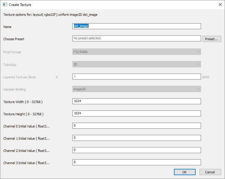
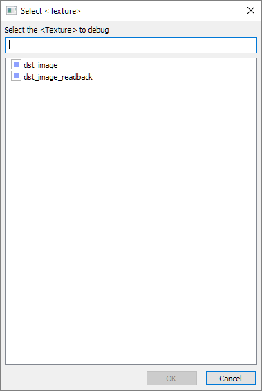
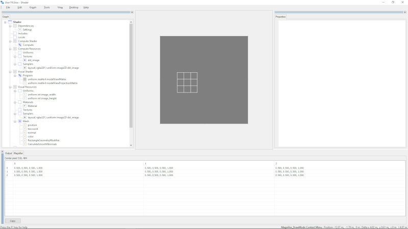
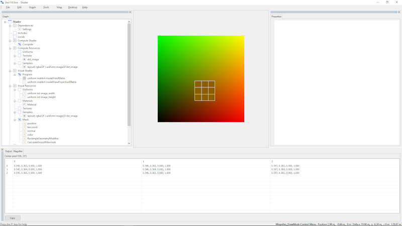
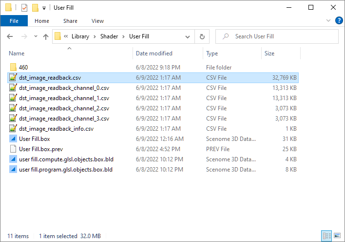
  3. Open the file dst_image_read_back.txt in a text editor.

    The contents look like this:

    
    0, 0, 0, 1, 0.0009765625, 0, 0, 1, 0.001953125, 0, 0, 1, 0.0029296875, 0, 0, 1, 0.00390625, 0, 0, 1, 0.0048828125, 0, 0, 1, 0.00585937...
    0, 0.0009765625, 0, 1, 0.0009765625, 0.0009765625, 0, 1, 0.001953125, 0.0009765625, 0, 1, 0.0029296875, 0.0009765625, 0, 1, 0.00390625...
    0, 0.001953125, 0, 1, 0.0009765625, 0.001953125, 0, 1, 0.001953125, 0.001953125, 0, 1, 0.0029296875, 0.001953125, 0, 1, 0.00390625, 0....
    0, 0.0029296875, 0, 1, 0.0009765625, 0.0029296875, 0, 1, 0.001953125, 0.0029296875, 0, 1, 0.0029296875, 0.0029296875, 0, 1, 0.00390625...
    0, 0.00390625, 0, 1, 0.0009765625, 0.00390625, 0, 1, 0.001953125, 0.00390625, 0, 1, 0.0029296875, 0.00390625, 0, 1, 0.00390625, 0.0039...
    0, 0.0048828125, 0, 1, 0.0009765625, 0.0048828125, 0, 1, 0.001953125, 0.0048828125, 0, 1, 0.0029296875, 0.0048828125, 0, 1, 0.00390625...
    0, 0.005859375, 0, 1, 0.0009765625, 0.005859375, 0, 1, 0.001953125, 0.005859375, 0, 1, 0.0029296875, 0.005859375, 0, 1, 0.00390625, 0....
    0, 0.0068359375, 0, 1, 0.0009765625, 0.0068359375, 0, 1, 0.001953125, 0.0068359375, 0, 1, 0.0029296875, 0.0068359375, 0, 1, 0.00390625...
    0, 0.0078125, 0, 1, 0.0009765625, 0.0078125, 0, 1, 0.001953125, 0.0078125, 0, 1, 0.0029296875, 0.0078125, 0, 1, 0.00390625, 0.0078125,...
    0, 0.0087890625, 0, 1, 0.0009765625, 0.0087890625, 0, 1, 0.001953125, 0.0087890625, 0, 1, 0.0029296875, 0.0087890625, 0, 1, 0.00390625...
    0, 0.009765625, 0, 1, 0.0009765625, 0.009765625, 0, 1, 0.001953125, 0.009765625, 0, 1, 0.0029296875, 0.009765625, 0, 1, 0.00390625, 0....
    0, 0.0107421875, 0, 1, 0.0009765625, 0.0107421875, 0, 1, 0.001953125, 0.0107421875, 0, 1, 0.0029296875, 0.0107421875, 0, 1, 0.00390625...
    0, 0.01171875, 0, 1, 0.0009765625, 0.01171875, 0, 1, 0.001953125, 0.01171875, 0, 1, 0.0029296875, 0.01171875, 0, 1, 0.00390625, 0.0117...
    0, 0.0126953125, 0, 1, 0.0009765625, 0.0126953125, 0, 1, 0.001953125, 0.0126953125, 0, 1, 0.0029296875, 0.0126953125, 0, 1, 0.00390625...
    0, 0.013671875, 0, 1, 0.0009765625, 0.013671875, 0, 1, 0.001953125, 0.013671875, 0, 1, 0.0029296875, 0.013671875, 0, 1, 0.00390625, 0....
    0, 0.0146484375, 0, 1, 0.0009765625, 0.0146484375, 0, 1, 0.001953125, 0.0146484375, 0, 1, 0.0029296875, 0.0146484375, 0, 1, 0.00390625...
    0, 0.015625, 0, 1, 0.0009765625, 0.015625, 0, 1, 0.001953125, 0.015625, 0, 1, 0.0029296875, 0.015625, 0, 1, 0.00390625, 0.015625, 0, 1...
    0, 0.0166015625, 0, 1, 0.0009765625, 0.0166015625, 0, 1, 0.001953125, 0.0166015625, 0, 1, 0.0029296875, 0.0166015625, 0, 1, 0.00390625...
    0, 0.017578125, 0, 1, 0.0009765625, 0.017578125, 0, 1, 0.001953125, 0.017578125, 0, 1, 0.0029296875, 0.017578125, 0, 1, 0.00390625, 0....
    0, 0.0185546875, 0, 1, 0.0009765625, 0.0185546875, 0, 1, 0.001953125, 0.0185546875, 0, 1, 0.0029296875, 0.0185546875, 0, 1, 0.00390625...
    0, 0.01953125, 0, 1, 0.0009765625, 0.01953125, 0, 1, 0.001953125, 0.01953125, 0, 1, 0.0029296875, 0.01953125, 0, 1, 0.00390625, 0.0195...
    0, 0.0205078125, 0, 1, 0.0009765625, 0.0205078125, 0, 1, 0.001953125, 0.0205078125, 0, 1, 0.0029296875, 0.0205078125, 0, 1, 0.00390625...
    0, 0.021484375, 0, 1, 0.0009765625, 0.021484375, 0, 1, 0.001953125, 0.021484375, 0, 1, 0.0029296875, 0.021484375, 0, 1, 0.00390625, 0....
    0, 0.0224609375, 0, 1, 0.0009765625, 0.0224609375, 0, 1, 0.001953125, 0.0224609375, 0, 1, 0.0029296875, 0.0224609375, 0, 1, 0.00390625...
    0, 0.0234375, 0, 1, 0.0009765625, 0.0234375, 0, 1, 0.001953125, 0.0234375, 0, 1, 0.0029296875, 0.0234375, 0, 1, 0.00390625, 0.0234375,...
    0, 0.0244140625, 0, 1, 0.0009765625, 0.0244140625, 0, 1, 0.001953125, 0.0244140625, 0, 1, 0.0029296875, 0.0244140625, 0, 1, 0.00390625...
    0, 0.025390625, 0, 1, 0.0009765625, 0.025390625, 0, 1, 0.001953125, 0.025390625, 0, 1, 0.0029296875, 0.025390625, 0, 1, 0.00390625, 0....
    0, 0.0263671875, 0, 1, 0.0009765625, 0.0263671875, 0, 1, 0.001953125, 0.0263671875, 0, 1, 0.0029296875, 0.0263671875, 0, 1, 0.00390625...
    0, 0.02734375, 0, 1, 0.0009765625, 0.02734375, 0, 1, 0.001953125, 0.02734375, 0, 1, 0.0029296875, 0.02734375, 0, 1, 0.00390625, 0.0273...
    0, 0.0283203125, 0, 1, 0.0009765625, 0.0283203125, 0, 1, 0.001953125, 0.0283203125, 0, 1, 0.0029296875, 0.0283203125, 0, 1, 0.00390625...
    0, 0.029296875, 0, 1, 0.0009765625, 0.029296875, 0, 1, 0.001953125, 0.029296875, 0, 1, 0.0029296875, 0.029296875, 0, 1, 0.00390625, 0....
    0, 0.0302734375, 0, 1, 0.0009765625, 0.0302734375, 0, 1, 0.001953125, 0.0302734375, 0, 1, 0.0029296875, 0.0302734375, 0, 1, 0.00390625...
    0, 0.03125, 0, 1, 0.0009765625, 0.03125, 0, 1, 0.001953125, 0.03125, 0, 1, 0.0029296875, 0.03125, 0, 1, 0.00390625, 0.03125, 0, 1, 0.0...
    0, 0.0322265625, 0, 1, 0.0009765625, 0.0322265625, 0, 1, 0.001953125, 0.0322265625, 0, 1, 0.0029296875, 0.0322265625, 0, 1, 0.00390625...
    0, 0.033203125, 0, 1, 0.0009765625, 0.033203125, 0, 1, 0.001953125, 0.033203125, 0, 1, 0.0029296875, 0.033203125, 0, 1, 0.00390625, 0....
    0, 0.0341796875, 0, 1, 0.0009765625, 0.0341796875, 0, 1, 0.001953125, 0.0341796875, 0, 1, 0.0029296875, 0.0341796875, 0, 1, 0.00390625...
    0, 0.03515625, 0, 1, 0.0009765625, 0.03515625, 0, 1, 0.001953125, 0.03515625, 0, 1, 0.0029296875, 0.03515625, 0, 1, 0.00390625, 0.0351...
    0, 0.0361328125, 0, 1, 0.0009765625, 0.0361328125, 0, 1, 0.001953125, 0.0361328125, 0, 1, 0.0029296875, 0.0361328125, 0, 1, 0.00390625...
    0, 0.037109375, 0, 1, 0.0009765625, 0.037109375, 0, 1, 0.001953125, 0.037109375, 0, 1, 0.0029296875, 0.037109375, 0, 1, 0.00390625, 0....
    0, 0.0380859375, 0, 1, 0.0009765625, 0.0380859375, 0, 1, 0.001953125, 0.0380859375, 0, 1, 0.0029296875, 0.0380859375, 0, 1, 0.00390625...
    0, 0.0390625, 0, 1, 0.0009765625, 0.0390625, 0, 1, 0.001953125, 0.0390625, 0, 1, 0.0029296875, 0.0390625, 0, 1, 0.00390625, 0.0390625,...
    0, 0.0400390625, 0, 1, 0.0009765625, 0.0400390625, 0, 1, 0.001953125, 0.0400390625, 0, 1, 0.0029296875, 0.0400390625, 0, 1, 0.00390625...
    ...
    

Check OpenGL Extension Support

  1. Examine the hierarchy.
  2. Right click over the <Program> named Compute and select Query Extension... from the listed options.

    The application displays a dialog that allows you to enter the name of an extension.

    This is a picture of the query extension dialog.
  3. Type GL_ARB_compute_variable_group_size and click OK or hit ENTER when you are done. Make sure to type the exact name or the query will return false.

    Copy Text To Clipboard

    GL_ARB_compute_variable_group_size

    The software displays a popup message indicating whether or not the extension is supported by your GPU. You migth see a message that says GL_ARB_compute_variable_group_size is supported: false.

    This is a picture of the query extension results.

    It's important to know this because we can set these values in the application if the extension is supported. If the extension is not supported, then we know that we have to use the values for local_size_x, local_size_y, and local_size_z specified in the compute shader source.

Examine Workgroup Sizes

  1. Examine the hierarchy and find the <ProgramExecute> node named ExecuteCompute.

    This node is near the bottom of the graph.

  2. Move the mouse over the <ProgramExecute> node and a tooltip appears. This is a picture of the graph.

    You here you can see the Work Group Dimensions and Local Group Dimensions stored by the <ProgramExecute> node. If your GPU supports GL_ARB_compute_variable_group_size then you can set Local Group Dimensions by changing the values set by the <ProgramExecute> node. Otherwise you have to set the values of local_size_x, local_size_y, and local_size_z in the compute shader. The compute shader source code contains the declaration layout( local_size_x = 32, local_size_y = 32, local_size_z = 1 ) in;. This is where you set the values in the compute shader if your GPU does not support GL_ARB_compute_variable_group_size.

    These values reflect a core compute shader principle called occupancy. Workgroups share resources such as shared memory and memory barriers. Usually these values must be set and optimized differently for each compute shader workload.

  3. Select File » Save from the main menu.

Explore Directory Structure

  1. Select Tools » Deselect All from the main menu.
  2. Select File » Open Containing Folder from the main menu.

    The software opens the directory containing your new shader document. Each of these folders contains the shader code for the corresponding GLSL version. In this example, we created a GLSL shader for the highest version on your machine. For example, the shader code we want to find is in the 460 folder or similar. You might not need all of these variations, and you can delete variations that you don't need. Since this is a compute shader document, it supports GLSL versions from 400 to 460.

    This is a picture of the directory that contains your new shader document.
    File Description
    dst_image_readback.csvA text file containing the values stored in the <Texture> written by the compute shader.
    dst_image_readback_channel_0.csvA text file containing the values stored in 0-th channel of the <Texture> written by the compute shader.
    dst_image_readback_channel_1.csvA text file containing the values stored in 1-th channel of the <Texture> written by the compute shader.
    dst_image_readback_channel_2.csvA text file containing the values stored in 2-th channel of the <Texture> written by the compute shader.
    dst_image_readback_channel_3.csvA text file containing the values stored in 3-th channel of the <Texture> written by the compute shader.
    dst_image_readback_info.csvA text file meta-data about the <Texture> such as width, height, and min/max values per channel.
    User Fill.boxThe document that contains the compute shader we're working on.
    User Fill.box.prevA copy of the document that gets saved each time the shader is rebuilt.
    user fill.compute.glsl.objects.box.bldThis contains nodes representing the declarations in your shader. This document changes each time you rebuild the shader document.
    user fill.program.glsl.objects.box.bldThis contains nodes representing the declarations in your shader. This document changes each time you rebuild the shader document.

    New documents that manage shader source code elements and document dependencies are added to this directory by the application from time-to-time.

  3. Double click the folder named 460. This is a picture of the directory that contains your new shader source code.
    File Description
    user_fill_attributes.glslA struct containing the vertex attributes layout for this document. This is an ASCII file that can be opened in any text editor.
    user_fill_compute_shader.box.bldThe compute shader build file. A .BLD document contains nodes that represent GLSL items such as shader buffers and uniforms. This document is not created or managed by the user, but it can be opened with the Shader app and inspected.
    user_fill_compute_shader.glslContains the compute shader source code. This is an ASCII file that can be opened in any text editor.
    user_fill_fragment_shader.box.bldThe fragment shader build file. A .BLD document contains nodes that represent GLSL items such as shader buffers and uniforms. This document is not created or managed by the user, but it can be opened with the Shader app and inspected.
    user_fill_fragment_shader.glslContains the fragment shader source code. This is an ASCII file that can be opened in any text editor.
    user_fill_vertex_shader.box.bldThe vertex shader build file. A .BLD document contains nodes that represent GLSL items such as shader buffers and uniforms. This document is not created or managed by the user, but it can be opened with the Shader app and inspected.
    user_fill_vertex_shader.glslContains the vertex shader source code. This is an ASCII file that can be opened in any text editor.
  4. Close the Windows® Windows® folder and return to the Shader application.