This exercise teaches you how to create a new document, implement a GLSL shader module that performs edge detection, and then visualize the results with a fragment shader. Your GPU must support GLSL #version 400 or higher in order to complete this exercise.
The application displays a splash screen and then the application desktop appears. The main menu is composed of three items that contain commands relevant to the current context (which is an empty file). The interface changes when you create a new file or load a file from disk.
The software displays a wizard that allows you to specify the parameters of your new shader. The Profile shown below is 460 core, but you will see the highest GLSL version available on your machine. This should be 400 core or higher, but this exercise is designed to work on nearly any version of GLSL, including legacy versions like 120, 130, 140, or 150. NOTE: You will not see video or compute shader options in the wizard dialog if you do not have the video or compute add-on modules installed.
User Edge Detection
The application creates a new shader document and the main menu options change. You can see the hierarchy on the left, the rendered shader with geometry in the middle, and the property sheet on the right. Shader compiler error messages are shown in the output window below. The shader sets the fragment color to red and does no other work.
If the shader compiled successfully, the bottom of the output window shows you a message like the following: Compiling Program 0x000002B69B9DC7D0 0x0000000000000000 <Program>. ( The hexadecimal codes in your message may not match exactly. ) If the shader didn't compile, you might see the grid, a black square, or a white square, depending on your GPU and the nature of the error. Please send an email to support@scenomics.com if you need technical support.
This expands the graph so that you can see all the nodes.
NOTE: You can hover over each node icon, in the image below, for a description of the node and its function.
That covers the basic information about the graph.
Notice that you can see the GLSL version, profile, and source code locations. Many nodes, but not all of them, display useful information if you hover over them. We can see that this is running GLSL #version 400 as we requested when we created the document.
At the end of this exercise, we'll show you how to find all your shader source code.
The application displays a dialog that allows you to create a new include file
SPA_UserSobel.glsl
The software saves the file to disk and copies the file path to the Windows®clipboard. This means we can use CTRL + V to paste this into a file open dialog and open the file without searching.
The file SPA_UserSobel.glsl opens and you'll notice that it's empty.
#ifndef SPA_SOBEL
#define SPA_SOBEL
#if __VERSION__ < 130
#define KERN_PIXEL( _x, _y ) ( texture2D( sampler, texcoords + onePixel * vec2( _x, _y ) ) )
#else
#define KERN_PIXEL( _x, _y ) ( texture( sampler, texcoords + onePixel * vec2( _x, _y ) ) )
#endif
void SPA_ConvoluteSobel( sampler2D sampler, vec2 image_size, vec2 texcoords, vec3 kernel, out vec4 res )
{
vec2 onePixel = vec2( 1.0, 1.0 ) / image_size;
float dx = ( length( KERN_PIXEL( -1, -1 ) * kernel[0] +
KERN_PIXEL( -1, 0 ) * kernel[1] +
KERN_PIXEL( -1, +1 ) * kernel[2] )
-
length( KERN_PIXEL( +1, -1 ) * kernel[0] +
KERN_PIXEL( +1, 0 ) * kernel[1] +
KERN_PIXEL( +1, +1 ) * kernel[2] ) );
float dy = ( length( KERN_PIXEL( -1, -1 ) * kernel[0] +
KERN_PIXEL( 0, -1 ) * kernel[1] +
KERN_PIXEL( +1, -1 ) * kernel[2] )
-
length( KERN_PIXEL( -1, +1 ) * kernel[0] +
KERN_PIXEL( 0, +1 ) * kernel[1] +
KERN_PIXEL( +1, +1 ) * kernel[2] ) );
float val = length( vec2( dx, dy ) );
res = vec4( val, val, val, 1.0 );
}
// !SPA_SOBEL
#endif
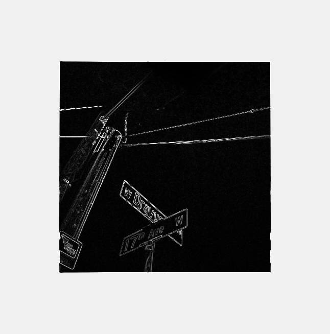
This is a fairly basic filter, but it will work very well for this example.
This displays a dialog that allows you to select GLSL shader source code (and any include files). The file path of the source item you select will be copied to the Windows® clipboard so you can open it in a text editor.
The file user_edge_detection_fragment_shader.glsl opens. Your fragment shader looks like this.
// #version 400
// The version number is automatically injected by the application.
// It is included above for reference purposes only.
#include <SPA_Version.glsl>
#include "user_edge_detection_attributes.glsl"
in Data { vertexData attributes; } DataIn;
out vec4 fragColor;
void main(void)
{
fragColor = vec4( 1.0, 0.0, 0.0, 1.0 );
}
// #version 400
// The version number is automatically injected by the application
// It is included above for reference purposes only.
#include <SPA_Version.glsl>
#include <Modules/SPA_Sobel.glsl>
#include "user_edge_detection_attributes.glsl"
uniform vec3 kernel = vec3( -1.0, 0.0, -1.0 );
uniform sampler2D edge_detection;
in Data { vertexData attributes; } DataIn;
out vec4 fragColor;
void main(void)
{
vec2 image_size = vec2( textureSize( edge_detection, 0 ) );
vec4 dst = vec4( 1.0, 0.0, 0.0, 1.0 );
SPA_ConvoluteSobel( edge_detection, image_size, DataIn.attributes.texcoord, kernel, dst );
fragColor = dst;
}
This is pretty standard GLSL source code. You'll notice includes and uniform declarations at the top of the shader and some very simple code in the fragment shader body, including a call into the GLSL module we just created.
Now we need to rebuild the document, configure uniforms, and add a texture.
Your shader is going to change. It will probably turn black, but it might be white or some other color. This is normal; we need to rebuild and configure resources to get a result on screen.
The software presents the build warning dialog, and warns you that document rebuilds can cause changes to shader appearance. During a rebuild, the shader source for all <Program> nodes and ( and <Program> nodes specified by <ProgramExecute> nodes ) in the document is traversed and built into a .BOX file that contains nodes representing all declared uniforms, uniform buffers, shader buffers, and structs. This information is used to automatically add the correct resources to the document and to delete obsolete resources.
The software builds the document and displays build information in the output window. Your file paths won't match the results shown below, but everything else will look the same.
--- <Building Project 'D:\Release6\Content\Library\Shader\User Edge Detection\User Edge Detection.box'> ---
Rebuilding Shader Resource Documents...
Rebuild succeeded: D:\release6\content\library\shader\user edge detection\400\user_edge_detection_vertex_shader.glsl
Rebuild succeeded: D:\release6\content\library\shader\user edge detection\400\user_edge_detection_fragment_shader.glsl
Updating document contents...
Adding to <UniformPaletteNode> 'Uniforms' <Float32VectorNode> 'uniform vec3 kernel'
Adding to <SamplerPaletteNode> 'Samplers' <SamplerNode> 'uniform sampler2D edge_detection'
Build completed.
Here's what the graph looked like before:
Here's what the graph looks like now. The changed areas are highlighted below. Certain types of shader declarations such as uniforms, shader buffers, and uniforms buffers will be created from the shader source code and converted into nodes that you see in the document below.
Examine the new <SamplerNode> named uniform sampler2D edge_detection. Notice that it has a red underline, indicating an error. Move your mouse over the node to see what the error is. ('The SamplerNode must have a valid Texture data source.')
The software displays a dialog that lets you load a texture with the correct topology for the <SamplerNode>. There is a list of folders that organize textures by pixel format.
IPF_8888_ARGB
edge_detection_src.png
The software creates a new <Texture> node and connects it to the <SamplerNode>. You can now see the results of the edge detection on the worksheet:
The hierarchy looks like this. Notice the new <Texture> node named edge_detection_src.
You can use the middle mouse button to zoom in on the image if you want ( or RIGHT MOUSE BUTTON + DRAG if you don't have a three-button mouse ). You can also hit ALT + 4 to show and hide all the three main user interface panels. You can also use View > Camera > Reset Camera to return to the default viewpoint. Use LEFT MOUSE BUTTON + DRAG to pan around the worksheet. Use RIGHT MOUSE BUTTON + DRAG to zoom in and out.
The software opens the directory containing your new shader document. Each of these folders contains the shader code for the corresponding GLSL version. For example: in this exercise, we created a GLSL version 400 shader, so the shader code we want is in the 400 folder.
New documents that manage shader source code elements and document dependencies are added to this directory by the application from time-to-time.
File | Description |
---|---|
USER_EDGE_DETECTION_ATTRIBUTES.GLSL | A struct containing the vertex attributes layout for this document. This is an ASCII file that can be opened in any text editor. |
USER_EDGE_DETECTION_FRAGMENT_SHADER.BOX.BLD | The fragment shader build file. A .BLD document contains nodes that represent GLSL items such as shader buffers and uniforms. This document is not created or managed by the user, but it can be opened with the Layout app and inspected. |
USER_EDGE_DETECTION_FRAGMENT_SHADER.GLSL | Contains the fragment shader source code. This is an ASCII file that can be opened in any text editor. |
USER_EDGE_DETECTION_VERTEX_SHADER.BOX.BLD | The vertex shader build file. A .BLD document contains nodes that represent GLSL items such as shader buffers and uniforms. This document is not created or managed by the user, but it can be opened with the Layout app and inspected. |
USER_EDGE_DETECTION_VERTEX_SHADER.GLSL | Contains the vertex shader source code. This is an ASCII file that can be opened in any text editor. |
This exercise is complete. Return to tutorials.