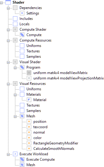
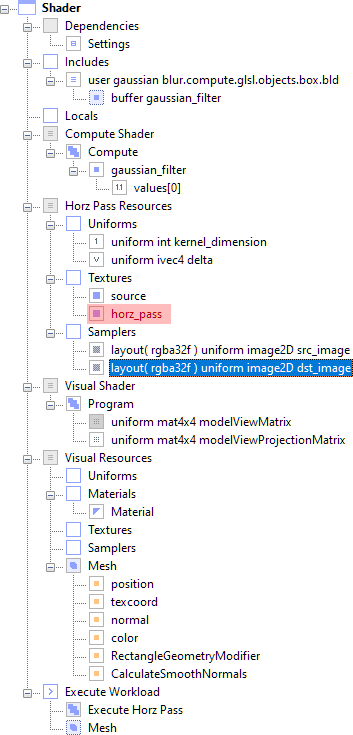
You need the following Simdify® modules to complete this exercise: Simdify® Free Edition, Simdify® Compute Module, Simdify® Buffer Module
In this exercise you'll learn to implement a compute shader that performs a Gaussian blur. This exercise requires GLSL version 400 or higher.
The application displays a splash screen and then the application desktop appears. The main menu is composed of three items that contain commands relevant to the current context (which is an empty document). As you will see, the interface changes when you create a new file or load a file from disk.
The software displays a wizard that allows you to specify the parameters of your new shader.
User Gaussian Blur
Note that your GPU must support GLSL 400 or higher to proceed. Otherwise you will not be able to set Add Compute Support to true and you cannot proceed with this exercise.
The application creates a new shader document and the main menu options change. You can see the hierarchy on the left, the rendered shader with geometry in the middle, and the property sheet on the right. Application messages, such as shader compiler error messages, are shown in the output window below.
If the shader compiled successfully, you should see a red square in the center of the worksheet.
This expands the graph so that you can see all the nodes. As you can see, this shader is a composite data structure made from a set of atomic types. The template document used to create the new file was built with a Simdify application named Graph.
That covers the basic information about the graph.
The software presents the rename dialog.
Horz Pass Resources
It's near the bottom of the graph. You may have to scroll to find it.
Execute Horz Pass
Note Using clear, precise names helps you learn faster and understand more.
It's near the top of the hierarchy.
This displays a dialog that allows you to select GLSL shader source code (and any include files). The file path of the source item you select will be copied to the Windows® clipboard so you can open it in a text editor.
This copies the absolute path to the compute shader source code to the Windows® clipboard. For example, a file path like the following: D:\Release6\Content\Library\Shader\User Gaussian Blur\460\user_gaussian_blur_compute_shader.glsl is copied to the clipboard.
This is the basic compute shader. Note that your #version 460 declaration might be different, depending on the highest GLSL version on your machine.
// #version 460
// The version number is automatically injected by the application.
// It is included above for reference purposes only.
#extension GL_ARB_compute_variable_group_size : enable
#ifdef GL_ARB_compute_variable_group_size
layout( local_size_variable ) in;
#else
layout( local_size_x = 32, local_size_y = 32, local_size_z = 1 ) in;
#endif
void main(void)
{
}
#extension GL_ARB_compute_variable_group_size : enable
#ifdef GL_ARB_compute_variable_group_size
layout( local_size_variable ) in;
#else
layout( local_size_x = 32, local_size_y = 32, local_size_z = 1 ) in;
#endif
layout( rgba32f ) uniform image2D src_image;
layout( rgba32f ) uniform image2D dst_image;
// Uniforms, constants, and buffers that
// configure the Gaussian kernel values,
// and allow us to dynamically resize the
// Gaussian kernel without changing the
// shader code.
uniform int kernel_dimension = 21;
int kernel_start = kernel_dimension / 2;
uniform ivec4 delta;
layout( shared ) buffer gaussian_filter
{
float values[];
};
void main(void)
{
ivec2 pos = ivec2( gl_GlobalInvocationID );
ivec2 src_dims = imageSize( dst_image );
vec4 accum_results = vec4( 0.0 );
int filter_index_x = 0;
//vec4 tempsrc = imageLoad( src_image, pos );
//vec4 tempdst = imageLoad( dst_image, pos );
for( int i = -kernel_start; i < kernel_start; ++i )
{
ivec2 read_coord = pos + delta.xy * i;
read_coord = clamp( read_coord, ivec2( 0 ), src_dims - 1 );
accum_results += imageLoad( src_image,
read_coord ) * values[ filter_index_x ];
++filter_index_x;
}
// Store the results in the second image sampler.
// We will perform the second pass on these values.
imageStore( dst_image, pos, accum_results );
}
This is the Gaussian blur compute shader. It performs the Gaussian blur in the horizontal or vertical direction depending on the value of uniform ivec4 delta. Since this compute shader only performs the blur in a single direction at a time, we'll need to implement two compute passes to compute the complete horizontal and vertical blur. We won't delve into the details of the blurring algorithm since you have the full source code and can examine this later.
Now that we've modified the shader source code, we'll need to rebuild the document so we can configure the resources specified by the shader.
Depending on your GPU, your on screen results may disappear or change when you return. Do not worry about this.
The software presents the build warning dialog.
The software warns you that rebuilds can cause changes to shader appearance. During a rebuild, the shader source for all <Program> nodes and ( and <Program> nodes specified by <ProgramExecute> nodes ) in the document is traversed and converted into a .BOX file that contains nodes representing all declared uniforms, uniform buffers, shader buffers, and structs. This information is used to automatically add the correct resources to the document and to delete obsolete resources.
The software rebuilds the shaders and adds resources to the document.
--- <Building Project 'D:\Release6\Content\Library\Shader\User Gaussian Blur\User Gaussian Blur.box'> ---
Rebuilding Shader Resource Documents...
Rebuild succeeded: D:\release6\content\library\shader\user gaussian blur\460\user_gaussian_blur_compute_shader.glsl
Rebuild succeeded: D:\release6\content\library\shader\user gaussian blur\460\user_gaussian_blur_vertex_shader.glsl
Rebuild succeeded: D:\release6\content\library\shader\user gaussian blur\460\user_gaussian_blur_fragment_shader.glsl
Updating document contents...
Creating <ShaderBufferBindNode> for <ShaderBufferNode> : buffer gaussian_filter
Adding to <UniformPaletteNode> 'Uniforms' <Int32Node> 'uniform int kernel_dimension'
Adding to <UniformPaletteNode> 'Uniforms' <Int32VectorNode> 'uniform ivec4 delta'
Adding to <SamplerPaletteNode> 'Samplers' <SamplerNode> 'layout( rgba32f ) uniform image2D src_image'
Adding to <SamplerPaletteNode> 'Samplers' <SamplerNode> 'layout( rgba32f ) uniform image2D dst_image'
Build completed.
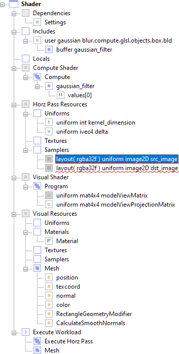
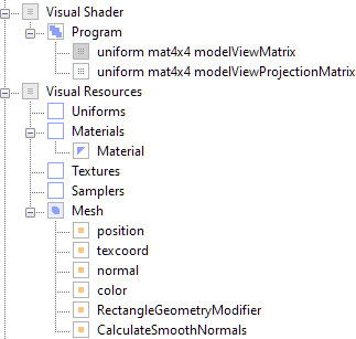
You can see new nodes in the graph.
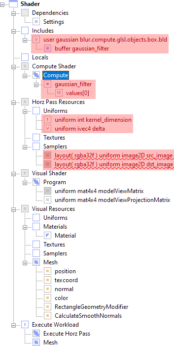
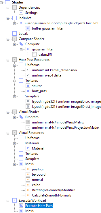
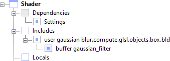
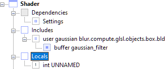
In Includes there is a <FileNode> named user gaussian blur.compute.glsl.objects.box.bld, and a <NodeLink> named buffer gaussian_filter that will store the Gaussian kernel values.
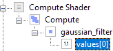
In Compute Shader there is a <ShaderBufferBindNode> named gaussian_filter, and a <Float32ArrayNode> named values[0] that will store the Gaussian kernel values.
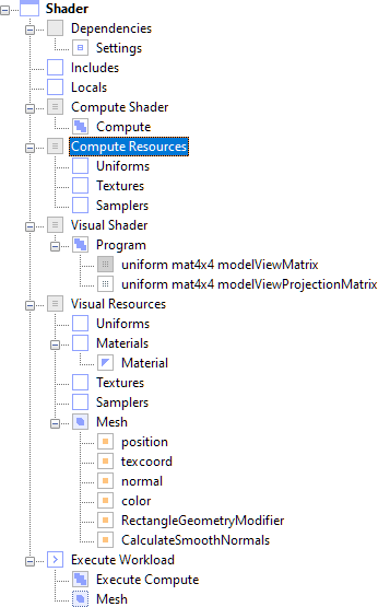
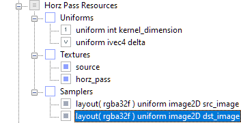
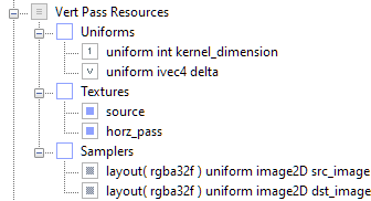
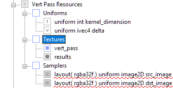
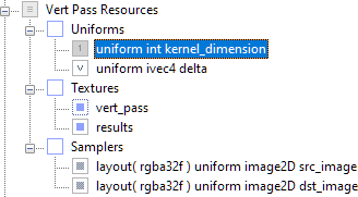
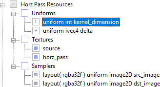
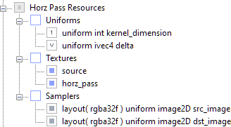
In the Horz Pass Resources section of the graph there is 
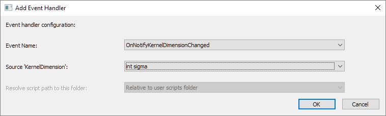
a new <Int32Node> named uniform int kernel_dimension, and a new <Int32VectorNode> named uniform ivec4 delta.
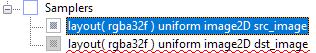
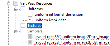
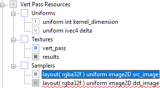
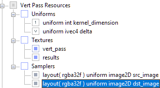
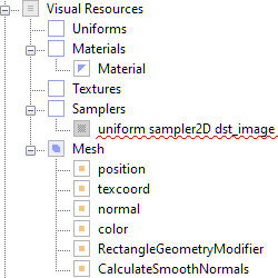
Finally there are two new <SamplerNodes> with red underlines named layout( rgba32f ) uniform image2D src and layout( rgba32f ) uniform image2D dst. Note that all the resource names exactly match the names of the declarations in the compute shader source code. In the Layout application, you can move the mouse over the new <SamplerNode> to see that these <SamplerNodes> need to be connected to <Texture> nodes.
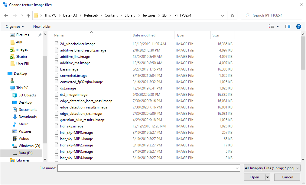
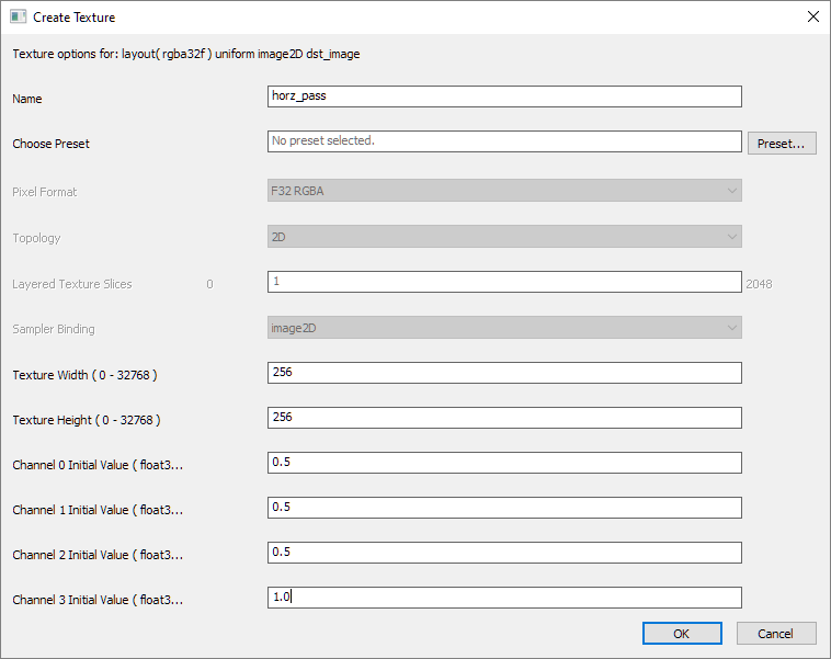
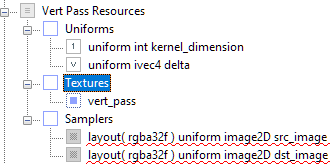
This is a common situation. You have samplers, but no textures. The Layout app allows you to create new textures that are compatible with a specific <SamplerNode>, or to load compatible textures from disk and connect them to a specific <SamplerNode>. We'll do both in this exercise.
The software displays a dialog box that displays a list of folders for each pixel format.
IPF_FP32x4
The dialog displays a list of textures:
IPF_FP32x4.image
The application creates a new <Texture> node and adds it to the document.
There is a new <Texture> node named IPF_FP32x4.
If you examine the hierarchy, you can see the <SamplerNode> icon is no longer grayed out. This means it is downloading the associated <Texture> to the GPU.
source
The software displays the create texture dialog. Note that some of the options are disabled. This is because the wizard knows what type of texture format, topology, and binding are required by the <SamplerNode> we selected. We've already specified the source texture, which the compute shader will read, and now we're going to create the destination texture into which the compute shader will write.
horz_pass
The software displays a dialog that allows you to load preset values from disk.
The channel values are automatically filled with the values 0.5, 0.5, 0.5, 0.5.
The software asks if you wish to save the texture to disk:
The software displays the file save dialog.
user_gaussian_blur_horz_pass.image
The software saves the new texture to disk and adds a <Texture> node named horz_pass.
There is a new <Texture> node named horz_pass.
The new <Texture> will store the results from the horizontal pass of the Gaussian blur. Note that the <SamplerNode> named layout( rgba32f ) uniform image2D dst_image was connected to the new <Texture> node named horz_pass when we created the new <Texture>.
This displays node properties in the property editor on the right side of the workspace.
This configures the compute shader to perform a horizontal blur.
It's near the bottom of the graph. You may have to scroll to find it.
The software presents the clone pass dialog to allow you to configure the clone operation.
Vert Pass Resources
Execute Vert Pass
The software adds new resources to the document.
You can see new nodes in the Vert Pass Resources section of the graph. This is essentially a clone of the resources used by the first pass. We're going to modify these to implement a second compute pass that will generate the vertical component of the blur.
The software displays a dialog that allows you to configure memory barrier flags. Note that only the most comonly used memory barrier flags are displayed here. You can double click the <MemoryBarrierNode> to set flags not shown here. You can also review the OpenGL documentation for these flags.
This memory barrier tells OpenGL to ensure image writes in the first pass are finished before the second pass starts.
The software presents a dialog that allows you to create a clone of an existing <Texture> in the document. You can create a direct clone which references the same file on a disk, a direct clone that references create a copy of the texture source file on disk, or a clone that creates a <NodeLink> (which is a hyperlink) to a <Texture> in this document. In this case, we'll create a <NodeLink> to an existing <Texture> in the document.
vert_pass
The software adds a <NodeLink> named vert_pass to the hierarchy. This allows us to use the results of the first pass of the compute shader (which is the horizontal blur) as the input to the second pass of the compute shader (which will perform the vertical blur).
A <NodeLink> is a hyperlink to another node, or you can also think of it as a pointer if you are more comfortable with that nomenclature. In this case, we are using a <NodeLink> because we want to use the results of the first compute pass (the horizontal blur) as the input for the second compute pass (the vertical blur). The <NodeLink> refers to the same OpenGL resource so that the compute shader can perform the vertical blur on the correct data.
You can distinguish <NodeLinks> from regular nodes by the dotted outline around the node icon. When you move the mouse over the node, a <NodeLink> to a <Texture> displays different hint text than than a <Texture>.
The software presents a dialog that allows you to create a clone of an existing <Texture> in the document. In this case, we'll create a <Texture> that points to a clone of an existing file on disk.
results
The software presents a dialog that allows you to set the name of the new file on disk.
user_gaussian_blur_vert_pass.image
The software adds a new <Texture> named results to the graph.
The new <Texture> icon is grayed out. This means that it is not resident on the GPU. Notice also that both <SamplerNode> icons are grayed out. This lets us know that the <SamplerNode> objects are not binding anything to the GPU.
The software presents a dialog that allows you to select a <Texture> or <NodeLink> to a <Texture>.
The hierarchy looks like this:
The new <Texture> icon is no longer grayed out. This means that it is resident on the GPU. Notice also that both <SamplerNode> icons are no longer grayed out. This lets us know that the <SamplerNode> objects are binding <Texture> objects to the GPU.
You'll notice the icon turns gray. This disables GPU download since we're already setting the value of this uniform in one place and we don't want or need to set it for the second compute pass.
This configures the compute shader to perform a vertical blur.
It's toward the bottom of the hierarchy.
This displays a dialog that allows you to select GLSL shader source code (and any include files). The file path of the source item you select will be copied to the Windows® clipboard so you can open it in a text editor.
This copies the absolute path to the compute shader source code to the Windows® clipboard. For example, a file path like the following: D:\Release6\Content\Library\Shader\User Gaussian Blur\460\user_gaussian_blur_compute_shader.glsl is copied to the clipboard.
This is the fragment shader. Note that your #version 460 declaration might be different, depending on the highest GLSL version on your machine.
// #version 460
// The version number is automatically injected by the application.
// It is included above for reference purposes only.
#include <SPA_Version.glsl>
#include <SPA_Constants.glsl>
#include <Modules/SPA_EditStateFragmentColorOverride.glsl>
#include "user_gaussian_blur_attributes.glsl"
in Data { vertexData attributes; } DataIn;
out vec4 fragColor;
void main(void)
{
fragColor = vec4( 1.0, 0.0, 0.0, 1.0 );
SPA_EditStateFragmentColorOverride( fragColor );
}
// #version 460
// The version number is automatically injected by the application.
// It is included above for reference purposes only.
#include <SPA_Version.glsl>
#include <SPA_Constants.glsl>
#include <Modules/SPA_EditStateFragmentColorOverride.glsl>
#include "user_gaussian_blur_attributes.glsl"
in Data { vertexData attributes; } DataIn;
uniform sampler2D dst_image;
out vec4 fragColor;
void main(void)
{
vec4 diffuse = texture( dst_image, DataIn.attributes.texcoord );
fragColor = diffuse;
SPA_EditStateFragmentColorOverride( fragColor );
}
The results on screen are going to change, turning black or white depending on your GPU. This is normal.
The software presents the build warning dialog.
The software rebuilds the shaders and adds resources to the document.
--- <Building Project 'D:\Release6\Content\Library\Shader\User Gaussian Blur\User Gaussian Blur.box'> ---
Rebuilding Shader Resource Documents...
Rebuild succeeded: D:\release6\content\library\shader\user gaussian blur\460\user_gaussian_blur_compute_shader.glsl
Rebuild succeeded: D:\release6\content\library\shader\user gaussian blur\460\user_gaussian_blur_vertex_shader.glsl
Rebuild succeeded: D:\release6\content\library\shader\user gaussian blur\460\user_gaussian_blur_fragment_shader.glsl
Updating document contents...
Adding to <SamplerPaletteNode> 'Samplers' <SamplerNode> 'uniform sampler2D dst_image'
You can see there is a new <SamplerNode> named uniform sampler2D dst_image below Visual Resources.
The software presents a dialog that allows you to select a <Texture> or <NodeLink> to a <Texture>.
It's near the top of the hierarchy.
We need to declare a local variable that will let us set the strength of the blur. Yes, we could declare this in our shader code, but it's not really necessary to do that.
The software displays a list of variable types.
The software adds an <Int32Node> as a child of Locals.
The software presents a dialog that allows you to edit the <Int32Node>. Note that
the <Int32Node> Name value is not the same as the name of the <Int32Node>.
Note that this is declared as an unsized array in the compute shader source code. We're going to implement event handling that controls the size of this array and changes the Gaussian kernel values based on changes to other nodes in the document.
The software displays a dialog that allows you to select predefined event handlers.
The dialog updates with settings specific to the event.
The software adds an event to values[0] and connects the event to the <Int32Node> named uniform int kernel_dimension. The node values[0] will update itself when it receives a notification that the <Int32Node> named uniform int kernel_dimension has changed.
The software displays a dialog that allows you to select predefined event handlers.
The software adds an event to uniform int kernel_dimension and connects the event to the <Int32Node> named int sigma. The node uniform int kernel_dimension will update itself when it receives a notification that the <Int32Node> named int sigma has changed.
The on-screen results now show us the image being written by the compute shader. You can see the Gaussian blur is correct. However because of the sizes of various <Texture> nodes, the blur only works for <Texture> nodes that match the dimensions of this source image, which is 256×256 pixels. We can create additional event handlers to resize images as needed so that this works with different sized source images. Note also that the Gaussian blur only works on 4-channel floating point textures. That is going to remain a requirement. It's better to write another shader if you need to apply a Gaussian blur to a different image format.
The software displays a dialog that allows you to select predefined event handlers.
The software adds an event to the <Texture> node horz_pass and connects the event to the <Texture> named source. The node <Texture> node named horz_pass will update itself when it receives a notification that the <Texture> named source has changed.
The software displays a dialog that allows you to select predefined event handlers.
The software adds an event to the <Texture> node named results and connects the event to the <Texture> named source. The node <Texture> node named results will update itself when it receives a notification that <Texture> named source has changed.
It's near the top of the hierarchy.
This displays node properties in the property editor.
The blurriness increases.
Right now the visual shader shows us the results, but we can also view the source <Texture> node and the first pass <Texture> node separately for debugging.
The software displays a list of compatible <Texture> nodes.
This is the source imagery used as the input to the Gaussian blur.
The software displays a list of compatible <Texture> nodes.
This is the horizontal pass generated by the compute shader.
The software displays a list of compatible <Texture> nodes.
This is the vertical pass generated by the compute shader, and it contains the final results of the Gaussian blur.
The software displays a list of compatible readback object types.
This will read the OpenGL® texture into a <Texture> object that we can inspect with the Magnifier tool.
The software creates the readback node items and adds them to the end of the document.
The Magnify editor appears.
If you move the mouse over the rendered geometry, you can see the values written by the compute shader.